Now that we are in the heating season, many burner service contractors are performing the annual clean-up or servicing of their customers’ appliances. What exactly does the serviceman do on these annual clean-ups? Let’s review a list of things that are usually involved.
It is essential in performing any professional task to have a good selection of tools and instruments that are standard to the trade. We will need:
- A complete set of hand tools.
- Pump testing gauges. 0-300 PSIG, and 0-30″ Hg for vacuum readings.
- Combustion test instruments for measuring CO2 or O2, smoke, draft, stack temperature and efficiency.
- A vacuum cleaner and assortment of soot snorkels and flue brushes.
- Of course, the service truck will be stocked with a variety of vital supplies, such as: furnace cement, various pump gaskets, pump strainers, filter elements, nozzles, electrode porcelains, blower fan belts, flue pipe and numerous other spare or replacement parts for the heating system. A well-stocked truck can eliminate unnecessary profit-robbing trips to the warehouse. There will be enough unscheduled visits with the best of planning.
Now, let us take a look at a typical clean and service. Many experienced technicians like to start the appliance and observe the performance to see just how it operates “as found.” Any obvious malfunctions can be diagnosed up front. If everything checks positive, then you are ready to start the methodical clean and service procedures. The following outline presents a sequence that is comprehensive and useful in accomplishing this service.
STEP 1
Fire test the unit. Is everything functioning normally? Combustion test is optional. Shut-off electrical power to appliance.
NOTE: Diagnose source of trouble and make repairs as needed. May need consultation with service manager or homeowner.
STEP 2
Remove the flue pipe. Clean thoroughly. Inspect chimney for blockage; clean as necessary. Check operation of barometric regulator. It should be clean of foreign matter and move freely.
NOTE: Squirrels and birds sometimes nest in chimneys causing restrictions. Also, loose bricks, mortar, leaves, twigs, and scale can accumulate. Replace any defective flue pipe.
STEP 3
Remove the flue collector box from the appliance. This permits access for secondary heat exchanger cleaning. Remove any baffles and thoroughly scrub the passages with a flue brush. Try to restore to “day one” condition for maximum efficiency. Carefully examine the surface area for cracks or other damage. Some units may have auxiliary clean-out ports for further exchanger access.
NOTE: Protect your respiratory system by wearing a painter’s mask or similar filtering system. Also, keep the vacuum cleaner running with the snorkel in the flue passage area. This catches much of the airborne particulate matter.
STEP 4
Older units permitted access to the combustion area for cleaning through a view or fire door. Sometimes the burner and front plate must be removed to do a complete job on the primary heating surfaces. Note the condition of the refractory and make needed repairs or replacements.
NOTE: Modern units have small viewports that may allow use of flue brushes and flexible soot snoots to clean this area. Suitable soot snorkels can be made from 3/4″ air conditioning drain hose or garden hose and wraps of duct tape for hose bushing.
STEP 5
Put everything back in place from above steps and seal all leaks or cracks with furnace cement or other appropriate sealants. Use sheet metal screws to secure all stack joints.
STEP 6
FURNACES: Examine the blower compartment. Check the air filters; oil the motor and blower shaft bearings; check V belt tension, pulley alignment; brush lint and dirt from blower wheel and other components. Check blower mounting to prevent noisy operation.
BOILERS: Oil circulator motor and bearing assembly. Check circulator coupling. Drain expansion tank as required. (These steps may not apply to all designs.)
STEP 7
For the BURNER SERVICE, we will outline several important steps to follow:
Remove the pump strainer cover and clean strainer. Replace cover gasket. Secure cover.
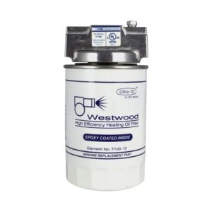
- Remove oil filter element and install new kit. Make sure canister is clean and tight. Any accumulation of sludge or water will necessitate checking tank for source of problem and remedy. Make sure all oil lines are clean, not kinked, and that all fittings are leak-free. USE FLARE FITTINGS – not compression style.
- Remove the firing assembly. Clean internal tubing and electrode porcelains if necessary. Examine insulators carefully for cracks or other defects. Replace nozzle with equivalent unit. DO NOT OVER-TIGHTEN! Set the electrodes to the manufacturer’s specifications.
- Examine the combustion head and clean any foreign material from all slots and holes. Make sure it is not damaged and is suitable for the firing range. Now the firing assembly can be put back into the burner.
- If the burner is still mounted in the appliance, use a flame mirror and flashlight to examine its condition and insertion. Most all burners should be 1/4″ recessed from the inside chamber wall. But, there are exceptions. Be sure to check manufacturer’s specs. Also, look for nozzle concentricity.
- Clean the transformer bushings and springs. Clean the cad cell surface and check the bracket alignment for good flame sighting.
- Using a small brush and vacuum cleaner snorkel, clean the air inlets and blower vanes. Restore to “like new” condition.
- Oil the burner motor if applicable. Use 3-4 drops of SAE 20 or 30 oil.
- Check all wiring for secure connections and insulation breaks or cuts.
- Prepare burner for combustion testing by bleeding all air from the pump. NO FROTH SHOULD BE VISIBLE FROM THE BLEED PORT for trouble-free operation. The safety lock-out can usually be timed during bleeding. The pump pressure test can now be made. Set for 100 PSIG minimum or that specified by the appliance manufacturer. Check the cutoff. The pressure should drop to approximately 80 PSIG and hold.
- Fire the burner. Use a flame mirror, where possible, to view the flame. It should be uniform and well-centered with no impingement anywhere.
STEP 8
The COMBUSTION TESTS come next. Calibrate your instruments and:
- Check draft over-fire. Set to specifications. Usually .02″ W.C. Next, measure the stack draft. It generally is slightly higher. Adjust draft regulator as needed.
- Measure smoke level. Adjust air to obtain a TRACE of smoke as steady-state conditions.
- Make the CO2 (or O2) tests. Say we have 13.0% CO2 (3.5% O2).
- Open the air adjustment to lower the CO2 by 1-1/2 percentage points (O2 increases by 2 percentage points).
- Smoke should now be zero and draft readings should still be adequate. You have built in a “cushion” to allow for seasonal variables.
- Take a gross stack reading. Subtract ambient and use your efficiency chart to determine the steady-state readings with the NET stack temperature and CO2 or O2 levels.
- Cycle the burner to ensure prompt ignition and smooth operation. Repeated cycling may be required to purge small air bubbles from nozzle adapter. All air is gone when the cutoff is clean with no after-squirt into the chamber or onto the air tube.
STEP 9
ALL safety and auxiliary controls should be tested for safe, reliable operation. Sometimes limit controls can be checked by simulating failure of blowers or circulators. Simply remove the power from the motors and cycle the burner until safety limits function to shut the burner OFF. Also, check automatic feed valves, low water cutoffs and pressure relief valves for dependable performance. Flush low water cutoff valves and verify water level at sight glass per manufacturer’s instructions on steam units. Always determine that the limit controls shut the burner down in the event of an operating control failure. Review the installation to see if it is up to current codes. Observe one complete burner operation cycle.
STEP 10
Make sure that the area surrounding the appliance is left in a cleaner condition than was found. Wipe all oil from the unit and floor. Spray oil odor neutralizer on residually-soaked areas. Clean evidence of “the black hand syndrome” from the appliance. Secure all covers and panels. Check all oil line fittings for leaks. Return all thermostat and temperature settings to the customer-desired level. Some companies have an attractive service label and logo to install on the finished job.
STEP 11
Consult with the service manager and/or homeowner regarding unusual findings or further required repairs not covered under the service agreement or contract. Arrange for follow-up at earliest convenience. Record all pertinent data on the service log for future reference. This can prove invaluable in solving system problems.
While this outline is by no means intended to be exhaustive or replace your present procedures, it should enable you to complement your methods and help you prepare for another season of professional service. The entire oil heating industry benefits from your diligent efforts in this regard.

