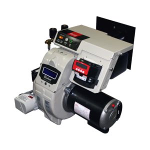
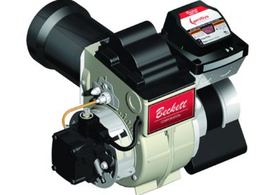
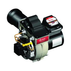
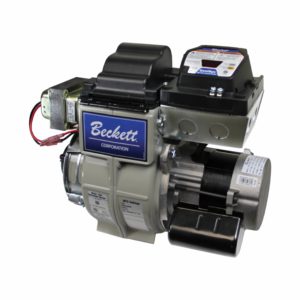
The Beckett CleanCut fuel unit has been developed as a joint effort with Suntec Industries. This fuel unit has a higher capacity than traditional American pumps: up to 4 GPH at 100-150 psig, or 3 GPH at 100 to 200 psig.
This technical bulletin discusses the advantages of the CleanCut fuel unit and provides important technical information.
OPERATION OF THE BECKETT CLEANCUT FUEL UNIT


- Instead of the traditional cone valve and diaphragm used in older fuel units, the Beckett CleanCut fuel unit uses a solenoid valve to control oil flow. In addition to improving actuator speed, the solenoid valve has a reduced number of parts and provides improved reliability.
Notice: This pump should be used with a control system that cycles the fuel solenoid valve. Some auto-start pressure washers may need a PD timer instead of the standard cordset, to obtain a clean light off. - At Startup: At startup the pump shaft is brought up to speed, at which time low-pressure oil from the gearset circulates around the closed pressure-regulating piston, through the open solenoid valve then back to the cover cavity (one-pipe) or the return line (two-pipe).
- During the Run Mode: At a signal from the control, power is applied to the solenoid’s coil, which activates the valve stem, blocking the oil’s return path. The blocked path allows the oil pressure to build at the piston to a point where the pressure exceeds the piston’s setting, which opens the piston and allows oil to fl ow through to the nozzle. As long as the pressure at the piston exceeds the rating of the piston spring, oil will continue to be supplied to the nozzle.
- At Shutdown: When the solenoid valve is de-energized, the pressure across the piston will again drop to a level where the piston closes and blocks flow to the nozzle. See Figure B.
BENEFITS OF A SOLENOID VALVE

- The quick acting solenoid virtually eliminates smoke at shutdown by allowing the burner air flow to complete combustion of any residual oil vapors in the combustion area before the motor coasts to a stop. As shown in Figure C, tests performed at Beckett show that this rapid shutoff contributes to less smoke at shutdown and reduced coil soot ups.
- The rapid cutoff is especially helpful if there are rumbles or pulsations at shutdown with certain applications. This is superior to the slower hydraulic pump cutoff, which is dependent upon the motor coast-down speed.
- Reduces wear and tear on switches, relays and the motor.
GENERAL INFORMATION

- The Beckett CleanCut fuel unit may be mounted in any position except
upside down with single pipe installations. - The Beckett CleanCut fuel unit may be installed with gravity feed or lift. The maximum allowable lift for a single pipe installation is 8 ft.
- When checking the Cleancut’s operating pressure, a reliable pressure gauge may be installed in either the bleeder port or the nozzle port. See Figure D. NOTE: the coil must be energized to obtain a reading using either set-up. Note: the bleeder port gauge reading is 5 psi higher than the reading at the nozzle port. The difference is less than 0.1 GPH at the Max nozzle rating of the pump.
- To check the cutoff function, deadhead a reliable pressure gauge onto the copper connector tube attached to the nozzle port. Run the burner for a short period of time. Shut the burner off – the pressure should drop and hold.
REMOTE TANK REQUIREMENTS
Pressurized loop or gravity feed installations must not exceed 3 psi on the inlet line or return line at the pump per NFPA 31. A pressure greater than 10 psi may cause damage to the shaft seal. All liquid fuel burning equipment (oil fi red) must be installed in accordance with the latest revision of NFPA 31 and all local codes and authorities having jurisdiction. These regulations take precedence over the guidelines contained in this bulletin.
WARNING: Do not install the bypass plug on one-pipe systems. To do so will cause immediate shaft seal failure and pressurized fuel oil spillage.
- Connect the inlet line to the pump inlet. Start the burner and open the bleed valve at least one-turn counter clockwise. Prime the system until all air bubbles have disappeared. Tighten the bleed valve securely. See Figure A.
WARNING: Long or oversized inlet lines may cause the pump to operate dry during initial priming. In such cases, injecting fuel oil into the pump gearset may assist in the priming. Be sure all fittings are airtight. To ensure this, apply oil-resistant pipe dope to the used and unused inlets, and both return fittings. NOTICE: Do not use Teflon tape or compression fittings.
- A vacuum gauge may be installed in either of the ¼” inlet ports. See Figure A. The Beckett CleanCut fuel unit should be used where the vacuum does not exceed 6” Hg on single pipe installations and 12” Hg on two-pipe installations. See Figures D and E.
- Two-pipe systems: install the bypass plug located in the plastic bag attached to fuel unit by removing the ¼” plug from return port. Insert and tighten the bypass plug. See Figure A. Attach return and inlet lines. Start burner. Air bleeding is automatic. Open the bleed valve for a faster bleed, if desired. The return line should terminate approximately 3-4” above supply line inlet to prevent recirculation of any air bubbles that may be present.

SERVICING INFORMATION
WARNING: Electrical Shock Hazard. Before servicing or installing the Cleancut solenoid disconnect the power supply to prevent electrical shock or equipment damage. Check the pressure washer manufacturer’s manual for correct solenoid wiring. See Figure F for typical wiring. All electrical work must be done in accordance with local and national codes.
- To determine if the valve coil needs to be replaced: Remove the cord set and use an ohmmeter to check the resistance of the coil. The resistance reading for the 120Vac coil should be 400 to 500 ohms; the 12Vdc coil – 15 to 25 ohms; the 240Vac coil – 1600 to 1800 ohms. If the meter shows an open circuit, replace the coil.
- To replace the valve stem and/or coil assembly see Figure G and follow these steps:
- Using a flat tip screwdriver, press the flat tip into the spring washer to prevent it from rotating. Using a 10mm wrench or adjustable wrench, remove the nut and spring washer.
- Remove the coil by lifting it straight up.
- Using a screwdriver, remove the two base plate screws.
- Remove the base plate by lifting it straight up.
- Remove brass tube assembly by pulling it straight up. Remove O-rings and discard.
- Install the new O-rings and new brass tube.
- Reinstall the coil following the above steps in reverse order, tightening each part as you go.

- Even though the operation of the fuel unit is satisfactory, a routine check of the pump strainer should be performed.
- Remove the pump cover by loosening the four cover screws. Pull the strainer out.
- Clean the pump strainer by using a brush and clean fuel oil or kerosene.
- Remove the old cover gasket and replace it with a new one.
- Install the cover and tighten the four cover screws evenly (same torque).
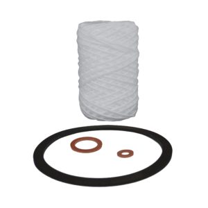
- If you are using the inlet into the side of the fuel unit, it is not necessary to remove the cover to check the strainer. Remove the inlet line and fitting to view the strainer through the inlet opening. If the strainer is clean at the inlet opening, it will be clean the rest of the way around. To replace the strainer and cover gasket use part number 51843U.

- To install a CleanCut fuel unit on Beckett Model AFG/ADC burners built before June 2001 see Figure H and follow these steps:
- Remove existing fuel unit and solenoid valves, if applicable, and appropriately dispose of them.
- Note the air shutter setting, then remove the air shutter, and set the shutter aside to be reinstalled.
- Remove the shutter tab by using a pair of side cutters and file sharp edges flush with burner surface. This will permit the shutter to be locked securely.
- Install the air shutter using the screw located below the pump. Adjust the shutter to the original air setting and tighten screw securely. Do not install the top shutter mounting screw; it will interfere with the solenoid on the fuel unit.
- Install the new CleanCut fuel unit and set the pump pressure according to the pressure washer manufacturer’s instructions.
- The Cleancut fuel pump simplifies the parts needed on your truck to repair most pressure washers because it can be used up to 4GPH firing rate and fits most brands of burner used in the pressure washer industry.
| CleanCut™ Part Numbers and Parts | |
| Description | Part Number |
| Fuel Unit – Beckett CleanCut – 120 volts AC | 2184405U |
| Fuel Unit – Beckett CleanCut – 12 volts DC | 2184402U |
| Fuel Unit – Beckett CleanCut – 240 volts AC | 2184403U |
| Valve Coil – 12 volts DC | 21754U |
| Valve Coil – 120 volts AC | 21755U |
| Valve Coil – 240 volts AC | 21756U |
| Valve Cord Set | 21807 |
| Valve Stem | 21877U |
| Strainer Kit | 51843U |
| PD Timer™ 120 volts AC | 21887U |

