Regional Sales Manager Request
Please fill out the form below to contact Beckett directly and we’ll get back to you within 24 hours.
There has been a significant increase in direct vent installations in recent years. These systems have benefited our industry in many ways, such as eliminating the need for a chimney in new home construction, reducing installation costs, providing fresh outdoor air for combustion, enabling sealed combustion, reducing standby draft losses and reducing system noise.
Certainly, direct vent installations represent a major advancement in technology and appliance design. The systems may require special intake air piping, exhaust piping, vent terminals, clearances, controls and code requirements. Unique and challenging service issues can arise. For instance, service technicians have requested information regarding how to handle the impact on combustion triggered by cold outside air, cold oil and exhaust gas recirculation into the combustion air intake that can occur under certain conditions. These factors can be problematic because they create conditions leading to random primary control lockouts.
When dealing with random lockouts, there are several important factors that need to be carefully examined before making changes to the heating system or burner specifications. We have provided these guidelines to assist you in professionally diagnosing and handling these issues.
NOTICE: This guide is provided as supplemental information and is not intended to supersede the appliance manufacturer’s published specifications. Always follow the appliance manufacturer’s instructions, strictly adhere to applicable codes, standards, ordinances and all authorities having jurisdiction.
Refer to appliance manufacturer’s specifications, burner installation manual, R.W. Beckett Residential Burner OEM Spec Guide part number 6711, or visit our website at www.beckettcorp.com. Verify the burner is set to the specifications for the specific appliance, as follows:
NOTE: The OEM Spec Guide air setting is the starting point. This setting must be adjusted to obtain the correct CO2 target.
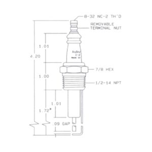
Figure 1. – Electrode Settings
| Burner Model & Heads | Electrode Tip Gap | Tip Height Above Nozzle Centerline | Tip Forward of Nozzle Face |
| NX | 5/32″ | 1/4″ | 3/32″ |
| Standard AFG – (F, L, V), AF- F, AFII – FBX | 5/32″ | 5/16″ | 1/16″ |
| Alternate AFG – L & V heads | 5/32″ | 1/4″ | 1/8″ |
| AFII – HLX/AF2 | 1/8 – 5/32″ | 1/4″ | 3/32″ |
Using combustion test instruments, measure the following combustion outputs and verify they are adjusted to the appliance manufacturer’s requirements:
NOTE: If the lockouts persist after completing the above tests, consider the following:
Before altering the system, make sure that any changes comply with the pump manufacturer’s instructions, the latest editions of NFPA 31, CAN/CSA-B139 and CSA B-140 in Canada and all authorities having jurisdiction.
Review the existing oil tank location (inside or outside) and the piping system (whether it is a one-pipe system or a two-pipe system) to see if cold oil is a potential issue. Two-pipe systems permit very little increase in oil temperature, since the oil circulates through the pipes at the pump gearset capacity, which is typically 17 to 20 gph. It may be possible to change from a two-pipe system to a one-pipe system, which only moves the nozzle flow rate. This greatly reduced fl ow volume allows the oil more time to gradually warm to the
indoor air temperature.
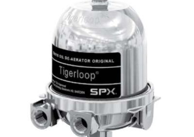
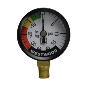
Evaluate the oil supply system by making the following checks:
Tech Note: Fuel oil will boil or de-gas at high vacuum levels, creating bubbles that enter the nozzle line causing a smoky or unstable fire and after-drip.
The vent system must comply with the appliance manufacturer’s specifications, the latest editions of NFPA 31, CAN/CSA-B139 and CSA B-140 in Canada and all authorities having jurisdiction.
Examine the vent system arrangement to check if cold air is a potential contributor to the random lockouts.
Review the installation of the vent terminals. Make sure the terminals are installed to comply with all specified and required clearances. Are there any obstructions or architecture that may impact recirculation of gases at the terminal? Cross-contamination of the flue gases with the incoming air can starve a fire (reduce oxygen content) and cause the burner control to go into lockout. It can also create soot/carbon build up.
Check the cad cell to verify a clean lens surface, correct bracket alignment and proper flame sensing.
If the system installation and cad cell sighting appears to be satisfactory, but lockouts persist, there is still a chance that cold air or a combination of cold air and cold oil might be causing flame instability or a nonlight-off condition. Sometimes, raising the pump pressure and using a slightly smaller nozzle will improve oil droplet atomization and stabilize the combustion, as outlined below.
We hope these guidelines provide valuable assistance, as you service, troubleshoot, effectively diagnose and resolve direct vent system issues that may arise in your service routine.
If you have any questions, please contact Beckett Technical Service at 1-800-645-2876 in the USA. (1-800-665-6972 in Canada) Our hours are 8 AM to 5 PM Eastern Time.
Also, we invite you to visit our website at: www.beckettcorp.com. Use Login: prof and Password: info, to enter our technical area. There are many features and downloads provided for service technicians to help stay up-to-date with our products and sharpen your troubleshooting skills.
| Nozzle flow rate U. S. gallons per hour of No. 2 fuel oil when pump pressure (psig) is: | |||||
| Nozzle size (rated at 100 psig) |
125 psi | 140 psi (factory std.) |
150 psi | 175 psi | 200 psi |
| 0.40 | 0.45 | 0.47 | 0.49 | 0.53 | 0.56 |
| 0.50 | 0.56 | 0.59 | 0.61 | 0.66 | 0.71 |
| 0.60 | 0.67 | 0.71 | 0.74 | 0.79 | 0.85 |
| 0.65 | 0.73 | 0.77 | 0.80 | 0.86 | 0.92 |
| 0.75 | 0.84 | 0.89 | 0.92 | 0.99 | 1.06 |
| 0.85 | 0.95 | 1.01 | 1.04 | 1.13 | 1.20 |
| 0.90 | 1.01 | 1.07 | 1.10 | 1.19 | 1.27 |
| 1.00 | 1.12 | 1.18 | 1.23 | 1.32 | 1.41 |
| 1.10 | 1.23 | 1.30 | 1.35 | 1.46 | 1.56 |
| 1.20 | 1.34 | 1.42 | 1.47 | 1.59 | 1.70 |
| 1.25 | 1.39 | 1.48 | 1.53 | 1.65 | 1.77 |
| 1.35 | 1.51 | 1.60 | 1.65 | 1.79 | 1.91 |
| 1.50 | 1.68 | 1.77 | 1.84 | 1.98 | 2.12 |
| 1.65 | 1.84 | 1.95 | 2.02 | 2.18 | 2.33 |
| 1.75 | 1.96 | 2.07 | 2.14 | 2.32 | 2.48 |
| 2.00 | 2.24 | 2.37 | 2.45 | 2.65 | 2.83 |
| 2.25 | 2.52 | 2.66 | 2.76 | 2.98 | – |
| 2.50 | 2.80 | 2.96 | – | – | – |
Informative and technical training resources from the leading experts in the heating industry
Have questions about our products? Looking for a solution to address a particular application? Looking to improve the overall productivity and profitability of your operation? Please don’t hesitate to reach out or schedule a no obligation, 1-on-1 consultation with a Beckett Technical Specialist — we’d love to help.
Beckett solutions are available through our network of Distributors, Independent Representatives, and Export Representatives all around the world.