Regional Sales Manager Request
Please fill out the form below to contact Beckett directly and we’ll get back to you within 24 hours.
o understand why oil burners need combustion air, let’s review the basics of how combustion occurs. Three elements must exist together in order for combustion to take place:
If any one of these three ingredients is missing, combustion will not take place.

A house which has a tight construction does not allow adequate airflow for combustion into the house. This problem is compounded by having multiple air-using appliances, fireplaces, and exhaust fans operating at the same time as the oil burner. A tightly sealed furnace / boiler room will create the same condition.
Another cause of the lack of combustion air is the environment in which the burner operates. If the burner draws air from an environment which has a large amount of dryer lint and animal hair, the air delivered to the combustion zone may be restricted due to clogging of the air openings, blower wheel, or combustion head.
One of the first noticeable signs of a lack of combustion air could be the odor of combustion products in the building. More than one air-using appliance running simultaneously may depressurize a tightly sealed building, causing a backdraft in one or more of the appliances. This condition could cause flue products to be pulled back through the chimney / exhaust system and into the building.
When combustion is deprived of the necessary oxygen, the correct ratio between the air and fuel changes to a fuel-rich, air-lean ratio. This causes an oil flame to become bright, orange, and soot-producing. In the case of a tightly sealed building, a burner which is operating cleanly might generate smoke as soon as another air using appliance is started.
Combustion test equipment is required to check the flue gas products. When you are performing the initial setup of a burner, if the flame does not burn cleanly, inadequate combustion air may be the cause. To determine quickly if this is the problem, open an outside door or window and perform the combustion and smoke tests again. If the flame now burns cleanly with the door or window open, lack of combustion air is most likely the problem.
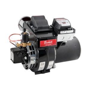
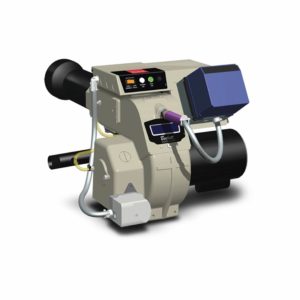
One method of compensating for insufficient air is to supply outside air directly to the oil burner. An outside air intake kit is available which allows the ductwork to be coupled directly to a Beckett model AF or AFG burner. This kit (#51747, shown below in Figure 2) replaces the Beckett outside air intake kit #5753. The boot can be mounted either horizontally or vertically, as shown in Figure 5 below. Be sure to follow the manufacturer’s instructions for installation of the Airboot™, intake air hood, air supply duct, vacuum relief valve, and exhaust terminal.


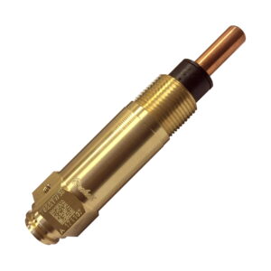
The vacuum relief valve (VRV) is installed in an unconfined area to provide a secondary opening in the duct system for combustion air supply. This is especially important in the event of damage or blockage of the intake air hood.
The VRV gate operates when changes occur in vacuum pressure generated between the air intake and the oil burner. The VRV gate remains closed during normal burner operation. If any blockage of the intake air hood or duct pipe occurs, or if significant changes in external building pressure occur, the increased negative pressure on the intake of the burner opens the VRV gate, which stabilizes and maintains proper air flow to the burner. The VRV gate closes again once the abnormal condition is corrected.
A burner operating in an unconfined space in a conventional frame, brick, or stone building will usually receive adequate air supply from normal air leakage into the building. However, if the building is tightly sealed, air must be supplied from the outside. A permanent opening to the outside (or to an area that receives air flow from the outside) is necessary, and the opening or openings must have a total free area of at least one square inch per 5000 Btu per hour, or 28 square inches per GPH of #2 fuel oil.
If the burner is located in a confined space such as a furnace or boiler room, the air requirements depend on the source of the ventilation and combustion air:
To summarize, for combustion air, an opening is needed that has at least 28 in.² of free space per GPH of #2 fuel oil. For ventilation air, two holes are needed, each with at least 140 in.² of free space per GPH (divide area by 2 for outside air; divide by 2 again for vertical ducts). Remember to take the total input of all air-using appliances into consideration when calculating the opening sizes. Refer to the NFPA 31 Standard (Chapter 1) and local codes for more information about combustion and ventilation air requirements.
*EXAMPLE CALCULATION: If an oil furnace is firing at 1.25 GPH and a water heater is firing at 0.50 GPH, two openings to the inside space of the building must each have at least 245 square inches of free area (1.25 GPH + 0.50 GPH = 1.75 GPH; 1.75 GPH x 140 square inches = 245 square inches). A 245 square inch opening would typically be 10″ x 25″ or 16″ x 16″.
Combustion air requirements are probably one of the most important and most neglected aspects of proper combustion. An adequate supply of combustion air is vital to the performance and continued operation of the heating unit. This outline of combustion air problems and solutions should assist you in maintaining a trouble-free, soot-free installation. The next time you take a deep breath, remember to check that the oil burner also has the capacity to “breathe” plenty of fresh air without restriction.
(Based upon 30 linear ft. of 4″ duct, two 90° elbows, and an Intake Air Hood) Read notes carefully!
AF Burner-Maximum Firing Rates for Negative Overfire Drafts (approx. -.02″ W.C.)
| HEAD | F0 | F3 | F4 | F6 | F12 | F16 | F22 | |||||||
| STATIC PLATE | G.P.H. | AIR DIAL SETTING | G.P.H. | AIR DIAL SETTING | G.P.H. | AIR DIAL SETTING | G.P.H. | AIR DIAL SETTING | G.P.H. | AIR DIAL SETTING | G.P.H. | AIR DIAL SETTING | G.P.H. | AIR DIAL SETTING |
| 2 – 3/4 U* | 0.75 | 195° | 1.14 | 260° | 1.19 | 250° | 1.37 | 260° | 1.56 | 260° | 1.75 | 260° | 1.83 | 260° |
| 3 – 3/8 U* | 0.69 | 225° | 1.07 | 260° | 1.14 | 250° | 1.28 | 260° | 1.49 | 260° | 1.57 | 260° | 1.70 | 260° |
| 3 – 3/8 R* | 0.62 | 250° | 0.95 | 260° | 1.10 | 250° | 1.20 | 260° | ||||||
| 3 – 5/8 R | 0.89 | 260° | ||||||||||||
AFG Burner-Maximum Firing Rates for Negative Overfire Drafts (approx. -.02″ W.C.)
| HEAD | F0 | F3 | F4 | F6 | F12 | F16 | F22 | F22 | F22 | F22 | ||||||||||
| STATIC PLATE | G.P.H. | AIR DIAL SETTING | G.P.H. | AIR DIAL SETTING | G.P.H. | AIR DIAL SETTING | G.P.H. | AIR DIAL SETTING | G.P.H. | AIR DIAL SETTING | G.P.H. | AIR DIAL SETTING | G.P.H. | AIR DIAL SETTING | G.P.H. | AIR DIAL SETTING | G.P.H. | AIR DIAL SETTING | G.P.H. | AIR DIAL SETTING |
| 2 – 3/4 U* | 0.75 | 55° | 1.25 | 90° | 1.35 | 120° | 1.58 | 260° | 1.84 | 260° | 2.05 | 260° | 2.23 | 170° | 2.33 | 270° | 1.96 | 270° | ||
| 3 – 3/8 U* | 0.75 | 115° | 1.21 | 110° | 1.35 | 145° | 1.54 | 260° | 1.78 | 260° | 1.90 | 260° | 2.05 | 260° | 1.00 | 270° | ||||
| 3 – 3/8 R* | 0.75 | 175° | 1.14 | 140° | 1.50 | 260° | ||||||||||||||
| 3 – 5/8 R | 1.10 | 155° | ||||||||||||||||||
AFG Burner-Maximum Firing Rates for Positive Overfire Drafts (approx. +.05” W.C.)
| HEAD | F0 | F3 | F4 | F6 | F12 | F16 | F22 | F22 | F22 | F22 | ||||||||||
| STATIC PLATE | G.P.H. | AIR DIAL SETTING | G.P.H. | AIR DIAL SETTING | G.P.H. | AIR DIAL SETTING | G.P.H. | AIR DIAL SETTING | G.P.H. | AIR DIAL SETTING | G.P.H. | AIR DIAL SETTING | G.P.H. | AIR DIAL SETTING | G.P.H. | AIR DIAL SETTING | G.P.H. | AIR DIAL SETTING | G.P.H. | AIR DIAL SETTING |
| 2 – 3/4 U* | 0.75 | 80° | 1.25 | 170° | 1.19 | 250° | 1.52 | 260° | 1.71 | 260° | 1.83 | 260° | 2.11 | 140° | 2.13 | 270° | 1.83 | 270° | ||
| 3 – 3/8 U* | 0.75 | 155° | 1.21 | 195° | 1.35 | 250° | 1.44 | 260° | 1.75 | 260° | 1.72 | 260° | 1.89 | 260° | 1.00 | 270° | ||||
| 3 – 3/8 R* | 0.75 | 235° | 1.14 | 240° | 1.35 | 260° | ||||||||||||||
| 3 – 5/8 R | 1.10 | 260° | ||||||||||||||||||
Notes:

Informative and technical training resources from the leading experts in the heating industry
Have questions about our products? Looking for a solution to address a particular application? Looking to improve the overall productivity and profitability of your operation? Please don’t hesitate to reach out or schedule a no obligation, 1-on-1 consultation with a Beckett Technical Specialist — we’d love to help.
Beckett solutions are available through our network of Distributors, Independent Representatives, and Export Representatives all around the world.