Regional Sales Manager Request
Please fill out the form below to contact Beckett directly and we’ll get back to you within 24 hours.
Combustion noise can occur in three major areas: at start-up, during the run cycle, and at shutdown. The following information is provided to help you effectively troubleshoot these areas.
Combustion noise at start-up is a rumble that is heard at the beginning of the call for heat.
DRAFT PROBLEMS: Follow the manufacturer’s specifications for draft measurements and adjust the barometric damper, if applicable.
LOW DRAFT: Inspect the heat exchanger for any restrictions. Look for restrictions in the flues or the chimney. Search to see if there are any cleanouts left open in the chimney.
HIGH DRAFT: Adjust the barometric damper, if applicable. If the draft remains high after the barometric damper has been adjusted, a second barometric damper could be considered. Sometimes a chimney cap can be helpful to lower the draft.
INADEQUATE STATIC PRESSURE:Verify the correct burner for the application. Consult the Beckett OEM (Original Equipment Manufacturer) Specification Guide (part number 6711) to ensure the proper burner specifications have been applied. If the appliance model is not found in the OEM Specification Guide, please contact Beckett Technical Service at 1-800-645-2876 for further assistance.

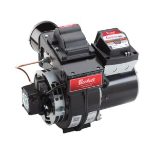
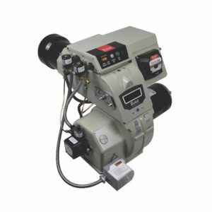
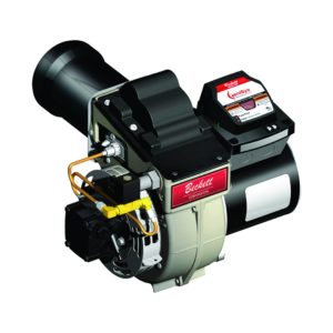
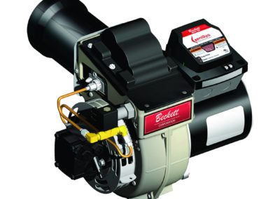
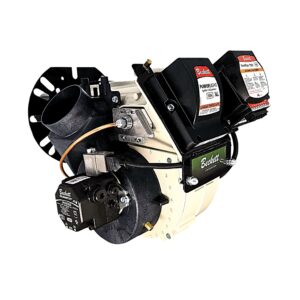
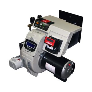
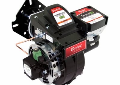
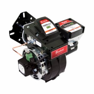
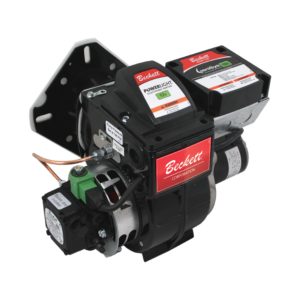
BURNER STATIC PRESSURE CAPACITY: The AF, AFG, and AFII burners differ in the amount of static pressure that each can produce. See Figure A. The blower in an oil burner provides a sustained volume of high air pressure on start-up to overcome any back pressure due to heat exchanger design or low draft.
AIRGUIDE: A common error made with the AFG and other high static pressure burners is the removal of the airguide from the housing. PLEASE DO NOT REMOVE THE AIRGUIDE FROM THE BURNER. If the airguide has been removed there will be extremely poor and erratic combustion.
GASKETS: Replace any defective gaskets, which can contribute to a loss of static pressure at burner start-up. Use Beckett gasket kit part number 51304 with AFG burners. See Figure B.

MOTORS: When replacing the motor, select a motor incorporating a closed face or a motor with ventilation openings that are within the circumference of the blower wheel. See Figure C. This will prevent a loss of static pressure at burner start-up and during the run cycle.
BLOWER WHEELS: When installing the blower wheel onto the AFG motor shaft, make sure it is positioned so that the distance between blower wheel backplate and motor face is 3/64″ ± 1/64″. A larger distance than what is specified may also contribute to a loss of static pressure.

ELECTRODES NOT POSITIONED CORRECTLY: Proper electrode settings are essential. See Figure D. Beckett offers a multi-purpose T500 gauge to assist you in making proper electrode settings.

EXCESSIVE COMBUSTION AIR: The burner must be adjusted to have the proper air-to-fuel ratio. Follow these four steps to properly adjust the burner:
HIGH OIL VISCOSITY: Viscosity is resistance to flow. Lower temperatures increase the oil viscosity, causing a significant impact on the ignition of the oil droplets.
This condition can be improved by reducing the nozzle size (gph) while increasing the pump pressure (psig) to obtain the required firing rate for the application. See Figure E. This will produce smaller droplets of fuel which are easier to vaporize and ignite.
The use of a nozzle line heater will help a cold oil start. Use Beckett Start Helper part number 51621.
Blending No. 2 fuel oil with 25% or more of No. 1 fuel oil (kerosene) will lower the viscosity and pour point.

Pulsations are caused by a loss of flame stability during the burner run cycle.
EXCESSIVE COMBUSTION AIR: A properly adjusted oil burner can eliminate pulsations. For proper burner adjustments, refer to “Excessive Combustion Air” on page 2.
OIL SUPPLY PROBLEMS: Loose or defective fittings can cause air leaks that can contribute to pulsations during the burner operating cycle. This could be due to air that is pulled in through the oil supply and purged through the nozzle, causing an erratic spray pattern. Air leaks can be the result of using compression fittings. NEVER USE COMPRESSION FITTINGS IN AN OIL SUPPLY SYSTEM.
GASIFICATION: Froth or bubbles are caused by some form of internal restriction in the oil supply line, such as a plugged fuel filter, a kink in the supply line, or sharp burrs on oil fittings. Gasification can also be caused by high vacuum in the oil supply. Consult the pump manufacturer’s specifications for line sizing and maximum lift conditions.
There are several methods that can be used to locate air leaks and bubbles. Listed below are four common procedures:
For more information on locating air leaks and gasification, refer to the Beckett technical bulletin part number 664822 entitled Successfully Locating Suction Line Leaks.
IMPROPER BURNER SPECIFICATIONS: The burner must be properly configured for the application. Consult the Beckett OEM Specification Guide (part number 6711) to be sure that the burner model, retention head, nozzle, pump pressure, solenoid valve, static plate, stop screw, head protector, low firing rate baffle, blower wheel, etc., are what have been specified.
Combustion noise at shutdown occurs at the end of the operating cycle and is characterized by an audible rumble.
PUMP CUTOFF PROBLEMS: Rumbles can occur at burner shutdown due to the cutoff of the fuel pump not holding under pressure.
SLUGGISH CUTOFF: This can easily be checked by dead-heading a reliable oil pressure gauge in the copper connector tube. See Figure E. DO NOT INSTALL THE OIL PRESSURE GAUGE IN THE OPTIONAL GAUGE PORT FOR THIS CUTOFF TEST. All fittings must be tight. Start the burner. Adjust the pump to the specified pressure and shut the burner off. The cutoff pressure is typically 20% lower than the operating pressure level. If the cutoff is sluggish or significantly lower than the 20% level, but still holds, replace the pump or install a solenoid valve.

ELECTRODES NOT POSITIONED CORRECTLY: Proper electrode settings are essential. See Figure D. Beckett offers a multi-purpose T500 gauge to assist you in making proper electrode settings.
EXCESSIVE COMBUSTION AIR: The burner must be adjusted to have the proper air-to-fuel ratio. Follow these four steps to properly adjust the burner:
DEFECTIVE CUTOFF SEAT: To check for a defective or obstructed cutoff seat, follow the instructions as outlined in, “Sluggish Cutoff”. If the pump pressure slowly drops to 0 psig, replace the pump.
AIR TRAPPED IN NOZZLE LINE: During burner operation, trapped air is compressed to a smaller size at operating pressure. This is typically 7-10 times atmospheric pressure (atmospheric pressure is approximately 14.7 psi). At burner shutdown, the small compressed bubble rapidly expands 7-10 times, to its original size at atmospheric pressure forcing oil to squirt from the nozzle. See Figure G. Since the blower wheel is coasting to a stop, there is insufficient air to completely burn this expelled fuel, resulting in a rumble at shutdown. There are several factors that can contribute to this condition:

When the nozzle line is removed for service, air replaces the oil that is drained from the nozzle line. This air mass will be broken into smaller bubbles and purged from the system by cycling the burner numerous times.
Servicing the oil supply system allows air to accumulate. Make sure all fittings are leak-tight after servicing the filter or other components. Bleed the pump until all bubbles have been purged from the system.
If the oil tank becomes empty, air will be introduced into the oil supply. Bleed the pump until all bubbles have been purged from the system.
Air leaks and gasification can lead to rumbles at shutdown. Gasification reacts the same way as an air leak. Please refer to “Pulsations” on page 3 to assist in solving this problem.
Hopefully, we have provided you with information that will help you understand and resolve rumbles and pulsations. Other potential causes may exist. The use of solenoid valves and controls with pre-purge and post-purge functions can also provide solutions. Beckett offers a number of technical bulletins to assist you in solving service-related problems.
Informative and technical training resources from the leading experts in the heating industry
Have questions about our products? Looking for a solution to address a particular application? Looking to improve the overall productivity and profitability of your operation? Please don’t hesitate to reach out or schedule a no obligation, 1-on-1 consultation with a Beckett Technical Specialist — we’d love to help.
Beckett solutions are available through our network of Distributors, Independent Representatives, and Export Representatives all around the world.