Regional Sales Manager Request
Please fill out the form below to contact Beckett directly and we’ll get back to you within 24 hours.
Our last issue addressed the electrical areas of the ignition system. This issue discusses two related systems that also can be contributing factors: The air and the oil handling systems.
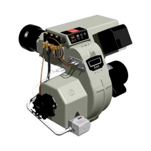
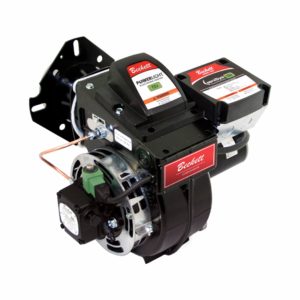
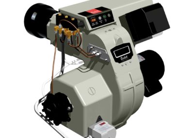
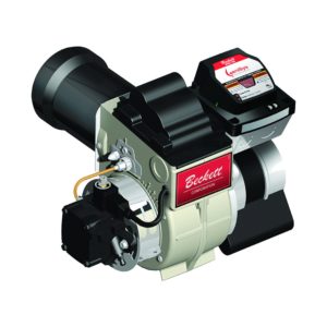
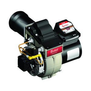
An oil burner delivers adequate combustion air over a wide range of firing rate inputs. Understanding the role of each component can help in solving some delayed ignition problems.
The blower wheel is selected to deliver the required air for combustion. Its rotation is fixed as is the number of blades, diameter and width. Replacements must be capable of equal performance.
The combustion head is engineered to fire over a specified range. Should the maximum nozzle size be exceeded, there will not be enough air for clean combustion. The increased air velocity through the head could “blow” the oil spray further away from the ignition arc, creating hard starts and pulsation.
Below its minimum nozzle size, the ratio of air-to-fuel is unbalanced resulting in poor flame retention. This can make ignition more difficult due to inadequate mixing and an unstable flame front.
Always operate within the specified head ranges. Make sure there is no damage to the head and that foreign matter is not restricting slots or openings.
What role does the static plate play? It is sometimes necessary for static pressure from the blower to build, thus forcing uniform air to the outside areas of the head. This allows less velocity down the center where ignition takes place.
Some combinations do not require a static plate. A centering device, or SPIDER, is used instead of a static plate. (Consult Manufacturer’s Specifications.)
The right amount of combustion air is necessary. When adjusting oil burners, measure the over-fire draft. It should be -.01 to -.02″ W.C. or that recommended by the appliance manufacturer. For extreme draft, install an appropriately-sized barometric damper. If insufficient, consider a draft inducer.
Check the smoke level. Adjust the air until a TRACE of smoke can be seen on the filter paper. At the TRACE level, take a flue gas sample. Let’s assume you have 13.0% CO₂ or 3.5% O₂. Now, add more air until this becomes 12.0% CO₂ or 4.5% O₂ with zero smoke. Not only have you built a cushion to accommodate adverse variables, but you should have the right amount of air for good ignition.
Cold combustion air can create problems. The colder air (temperatures below 50°F) will surround the oil droplets, lowering their temperature and increasing the energy required for vaporization and ignition. There could be extended delays or, at the extreme, burner lock-outs whenever the flame is not established within the safety timing. Always restore such oil-soaked chambers to a safe condition before resetting the safety switch.
The fuel pump, driven by the burner motor draws oil from the storage tank, provides some filtration, regulates the operating pressure and produces a positive cutoff at the end of the cycle. The pump can be involved in delayed ignition even though it is not the cause. For example, if the oil lines are too long, or have suction leaks, the pump may be blamed for not delivering adequate pressure or for having a bad cutoff.
Always make sure the supply piping is sized correctly. (Consult Manufacturer’s Charts.) Use only dependable flare fittings. Install an oil filter near the pump inlet. Bleed all air from the system and determine that there are no suction line leaks before leaving the job.
The quality of oil is important. No. 2 oil can vary in consistency, as shown by random sampling studies. Some oils can be higher in viscosity, that is, having greater resistance to flow. This reduces the nozzle’s ability to atomize the oil into small droplets. The larger the oil droplets, the more difficult they are to ignite and burn.
Water can get into the oil due to condensation, negligent storage practices, loose fillbox lids or damaged gaskets and leaks in underground tanks that allow table water to seep in. Small amounts drawn into the pump and discharged to the nozzle can cause delayed ignition. Clean the system thoroughly, making necessary repairs.
Dirt, bacteria and sludge can also contaminate oil storage tanks. The system should be thoroughly cleaned and treated with suitable chemical agents to disperse the residue that can partially clog piping filters, strainers and nozzles, precipitating ignition problems.
Air trapped in the nozzle adapter can affect the initial spray characteristics when pressurized. The resultant momentary erratic spray can cause noisy flutters on start-up and rumbles on shutdown. Sometimes puff-backs occur.
It requires skill to locate the source of air infiltration, but it is essential in solving this problem. If air froth is visible in the oil being bled from the pump bleed valve or nozzle port discharge tubing, you have not found the leak. Carefully examine fittings, gaskets, seals and valve stem packing in the supply system. Pressure/vacuum check the piping if necessary.
EFFECTS OF PRESSURE ON NOZZLE FLOW RATE
NOZZLE FLOW RATES IN GALLONS PER HOUR (Approx.)
| NOZZLE RATING AT 100 PSI | 80 PSI | 120 PSI | 140 PSI | 160 PSI | 200 PSI | 300 PSI |
| .50 | 0.45 | 0.55 | 0.59 | 0.63 | 0.70 | 0.86 |
| .65 | 0.58 | 0.71 | 0.77 | 0.82 | 0.92 | 1.12 |
| .75 | 0.67 | 0.82 | 0.89 | 0.95 | 1.05 | 1.30 |
| .85 | 0.76 | 0.93 | 1.00 | 1.08 | 1.20 | 1.47 |
| .90 | 0.81 | 0.99 | 1.07 | 1.14 | 1.27 | 1.56 |
| 1.00 | 0.89 | 1.10 | 1.18 | 1.27 | 1.41 | 1.73 |
| 1.10 | 0.99 | 1.21 | 1.30 | 1.39 | 1.55 | 1.90 |
| 1.20 | 1.07 | 1.31 | 1.41 | 1.51 | 1.70 | 2.08 |
| 1.25 | 1.12 | 1.37 | 1.48 | 1.58 | 1.76 | 2.16 |
| 1.35 | 1.21 | 1.48 | 1.60 | 1.71 | 1.91 | 2.34 |
| 1.50 | 1.34 | 1.64 | 1.78 | 1.90 | 2.12 | 2.60 |
| 1.65 | 1.48 | 1.81 | 1.95 | 2.09 | 2.33 | 2.86 |
| 1.75 | 1.57 | 1.92 | 2.07 | 2.22 | 2.48 | 3.03 |
| 2.00 | 1.79 | 2.19 | 2.37 | 2.53 | 2.82 | 3.48 |
| 2.25 | 2.01 | 2.47 | 2.66 | 2.85 | 3.18 | 3.90 |
| 2.50 | 2.24 | 2.74 | 2.96 | 3.16 | 3.54 | 4.33 |
| 2.75 | 2.44 | 3.00 | 3.24 | 3.48 | 3.90 | 4.75 |
| 3.00 | 2.69 | 3.29 | 3.55 | 3.80 | 4.25 | 5.20 |
| 3.25 | 2.90 | 3.56 | 3.83 | 4.10 | 4.60 | 5.63 |
| 3.50 | 3.10 | 3.82 | 4.13 | 4.42 | 4.95 | 6.06 |
| 4.00 | 3.55 | 4.37 | 4.70 | 5.05 | 5.65 | 6.92 |
| 4.50 | 4.00 | 4.92 | 5.30 | 5.70 | 6.35 | 7.80 |
| 5.00 | 4.45 | 5.46 | 5.90 | 6.30 | 7.05 | 8.65 |
| 5.50 | 4.90 | 6.00 | 6.50 | 6.95 | 7.75 | 9.52 |
Figure 1
Cold oil temperatures create a narrower spray angle, higher viscosity and larger oil droplets which are difficult to vaporize and ignite. Usually, little can be done to relocate the tank and piping to a warmer zone. Increasing the pump pressure to 140 PSI and reducing the nozzle by one size (example 1.0 GPH reduced to .85) will help. This greater pressure produces smaller droplets. (See Figure 1.)
If you choose this method, be sure to leave a tag on the pump describing what you have done so that the next service technician will be fully aware of the higher pressure. Single pipe systems will reduce bypass oil flow and allow oil to be warmed in the pump. Use them, if possible, or look for other means to allow the oil to be warmed before entering the fuel pump.
Delayed oil solenoid valves provide times for adequate air flow and ignition arc establishment BEFORE oil is delivered to the nozzle. Their use can reduce ignition problems.
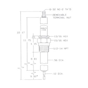
The nozzle, partially plugged with foreign matter, can have an unbalanced pattern that concentrates away from the ignition arc. Its relationship to the combustion head should be checked. For example, this “Z” dimension is 1-1/8″ from the nozzle face to the flat head surface with Beckett AF burners. Too far back could result in oil impinging on the I.D. of the head and too far forward could short the electrodes to the head.
The nozzle should be concentric (centered) with the head I.D. The spray angle is important. Generally, Beckett burners utilize the 60º-80º nozzles. If the spray is too narrow, the ignition arc will not be able to reach it effectively. If the angle is too wide, the droplets could impinge on the radial cup of the head and even upon the electrode tips. A carbon bridge could form and cause ignition problems.
Delayed ignition problems can become rather complex. Hopefully, this and our December 1990 issue will enable you to quickly determine which area to pursue in order to identify and resolve the problem.
Informative and technical training resources from the leading experts in the heating industry
Have questions about our products? Looking for a solution to address a particular application? Looking to improve the overall productivity and profitability of your operation? Please don’t hesitate to reach out or schedule a no obligation, 1-on-1 consultation with a Beckett Technical Specialist — we’d love to help.
Beckett solutions are available through our network of Distributors, Independent Representatives, and Export Representatives all around the world.