Nozzle afterdrip has been a concern among servicemen for quite sometime. There are three basic causes for afterdrip. They are:
- A defective pump shut-off valve.
- Air entrapped in the nozzle line assembly.
- Oil expansion in the nozzle line assembly, due to radiated heat at shutdown.
The first is relatively easy to diagnose. Here is a recommended test that will enable you to check the fuel unit shut-off characteristics.
- Install a reliable pressure gauge in the nozzle discharge port of the fuel unit. A gauge with a pressure range of 0-150 PSI should suffice. Make sure that all threaded joints are adequately sealed and tight.
- Start the burner and let it run for the duration of the safety timing cycle. When it locks out, the pressure should drop from the operating level to roughly 20% less, or substantially above 0 PSIG and hold indefinitely. If it fails to stabilize and slowly descends to 0 PSIG, then check the gauge fittings for leaks. If none can be found, replace the pump.
Entrapped Air
If air gets trapped in the nozzle line or adapter, it will cause afterdrip. This is what typically happens:
- Air at atmospheric pressure is approximately 14.7 PSI, and is compressible.
- When air trapped in the adapter is subjected to 100 PSIG, it is compressed to roughly 7 atmospheres. (14.7 x 7 = 102.9) This reduces the air volume to nearly 1/7 of its “atmospheric” size.
- When the burner shuts off, the pressure eases back to atmospheric, and the air bubble expands back to 7 times its compressed volume.
- This rapid expansion pushes oil out of the nozzle until the internal pressure equals the atmospheric pressure.
- An afterdrip occurs for several seconds. Usually a small stream of oil squirts into the hot chamber. A small, smoky fire may result, which can lead to delayed ignition, sooted heat exchangers and the odor of oil fumes.
This condition is easily diagnosed by peering into the chamber upon burner shutdown and watching for the evidence of smoke and afterburn shortly after the main flame is extinguished. If there is no viewport, you can turn the power OFF and immediately tilt the transformer back and watch for the same evidence through the combustion head.
Air can be eliminated by making sure that the oil supply lines are properly installed to the pump manufacturer’s specifications. Use good flare fittings, but keep the number to a minimum. If the leak cannot be easily found, a more thorough pressure or vacuum test may have to be made on the piping. When the oil lines are leak-free, the oil delivery will be clear of froth and minute bubbles. You can check this at the nozzle discharge tube or at the bleed port.
Initial Installation
To help prevent afterdrip at the initial installation or at nozzle change time, pour some clean oil into the nozzle adapter while holding your thumb over the rear nozzle tube fitting. When the tube is nearly full, install the nozzle securely but do not over-tighten! With your thumb still blocking the opposite end, insert the assembly into the burner and quickly connect the pump discharge connector tube. Simple, but effective. Now you start from cycle one with very little air in the system. You do not have to wait for numerous cycles to eliminate the entrapped air bubbles.
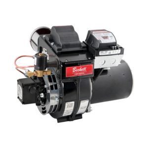
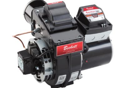
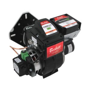
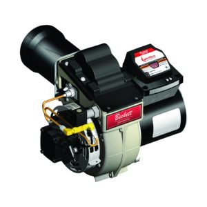
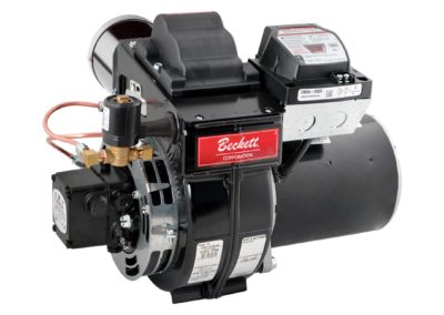
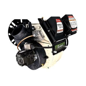
If you are working with a Beckett burner, it will have a built-in air vent plug. This device is inserted into the nozzle tube, rather than the adapter, so that it is always in place, even if someone changes the adapter. This plug has a small groove cut through its length at the top forcing high-velocity oil to pass through the reduced opening, thus breaking up large bubbles of air and purging the system quickly. Lower firing rate nozzles, however, do not allow a very large volume of oil to flow through the system, so air may be entrapped for longer duration. That is why many cycles may be required to eliminate all of the air.
Heat As A Major Contributor
Oil responds to heat in a very predictable way. For every degree F of rise in temperature, we get .04% expansion of volume. Of course, this is no problem during the operating cycle as long as it does not exceed 300°F, according to a leading nozzle manufacturer.
The afterdrip occurs when the burner shuts down and the temperature of the oil in the nozzle line and adapter begins to rise. The amount of temperature rise determines the amount of volumetric expansion of the oil.
Field experience shows that hard refractories, such as firebrick, tend to radiate more heat upon the nozzle and related components at burner shutdown. Therefore, the solution is to line an old refractory with a modern cerafelt or ceramic chamber liner. It will substantially reduce radiation due to its much lighter mass. Additionally, the cerafelt liner gives up its heat more readily during the OFF cycle. (See Figure 1.)
It, also, is good practice to wrap a sleeve of cerafelt around the last few inches of the air tube up to, but not exceeding the combustion head. This will reduce the nozzle temperatures and afterdrip.
Additional Tips
There are some additionally points to keep in mind. First make sure the burner is installed with a downward pitch so any afterdrip will run into the chamber and burn away during the next cycle. The second point is simply to know that a hydraulic cut-off normally produces at least one drop of oil per cycle. It’s usually unnoticed if the burner is pitched properly. That is why a small drain hole is punched in every combustion head to allow any oil accumulation to run forward and harmlessly drip into the combustion area.
Beckett burners are built with a slight downward pitch. However, if the installation is not level, or if the appliance mounting plate is not true, then the built-in angle of downward pitch can be quickly negated. One quick check is to pour a few drops of water from a small container such as a nozzle box, into the air tube when it is cool. The resultant flow will tell the story. An accurate pocket level placed into the air tube is another way. Usually, the problem can be easily corrected by raising the front of the appliance with appropriate shims.
After trying all of the above, you still could encounter some oil running back to the chassis and dripping onto the floor or vestibule shelf. Excessive radiation from the refractory can cause the oil to migrate uphill. This occurs under certain adverse conditions.
A solution that many have found to be effective involves applying a high temperature silicone rubber, such as 732 RTV Silastic by Dow Corning, to the air tube/burner chassis junction. First, thoroughly clean the bottom one third of the joint with a solvent, such as rubbing alcohol. When dry, apply the sealant. Some can be spread sparingly into the last couple of inches of the air tube seam to prevent any leakage here.
Now, when the afterdrip occurs, due to elevated “soak” temperatures during the OFF cycle, the oil cannot find an escape route. Subsequently, when the burner cycles again, the blower pressurizes the air tube and the oil film is forced back through the weep hole in the combustion head. While this condition is rare, this sealant approach can eliminate nuisance call backs due to oil dripping from the burner housing.
By following the above-mentioned guidelines, you will be able to successfully resolve the majority of your afterdrip problems.

